
GNSS Board Fails to Acquire Satellites: A Systematic Troubleshooting Guide
In GNSS-based systems, failure to acquire satellites is one of the most common issues encountered during integration and testing.
Based on COMNAV’s field support experience, this article summarizes a systematic and cost-effective troubleshooting approach, applicable to most OEM GNSS boards and modules.
The key principle is simple: exclude external factors first, then isolate board-level or module-level issues, progressing from low-cost checks to deeper hardware diagnostics.
1. Preliminary Verification: Communication and Output Status
Before hardware inspection, confirm that the GNSS board is functioning at a basic communication level.
1.1 Firmware Version Check
Ø Action:
Send the command log version via serial interface (default baud rate: 115200).
Ø Purpose:
Verify firmware version, module serial number (SN), and basic identification information.
Ø Expected behavior:
The command returns “OK! Command accepted”, and the reported firmware version matches the intended configuration.
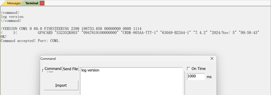
This step confirms that the processor, firmware, and serial communication are operating normally.
1.2 GPGGA Output Confirmation
Ø Action:
Send log gpgga ontime 1.
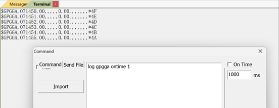
Expected behavior:
Continuous output of $GPGGA messages. If the satellite count 0, the board is powered and running but not tracking satellites.
This confirms that the issue is related to signal reception rather than firmware execution or other issues.
2. External Checks: Environment and RF Connections
In practical deployments, most “no satellite” issues are caused by environmental or RF path problems.
2.1 Comparative Test (Strongly Recommended)
Ø Action:
Replace the current board with a known-good board of the same model, keeping the antenna, cables, and environment unchanged.
Ø Interpretation:
l If the replacement board acquires satellites normally, external factors can be ruled out and internal checks should follow.
l If the replacement board also fails, the issue is very likely related to environment or RF connections.
This step significantly reduces troubleshooting time and uncertainty.
2.2 Antenna and Cable Inspection
Ø Installation environment:
Ensure the antenna has an unobstructed view of the sky. Indoor use, underground locations, or metal shielding will severely attenuate GNSS signals.
Ø Antenna condition:
Check for physical damage and connector integrity. Replace the antenna if any abnormality is suspected.
Ø RF cable:
Verify continuity with a multimeter. Cable breaks, oxidation, or excessive loss can prevent satellite acquisition even when the board is functioning correctly.
2.3 Power Splitter Considerations (If Applicable)
Ø Splitters with DC pass / bias-tee:
Confirm that the splitter is properly powered, or that the GNSS board supplies antenna bias voltage through a DC-pass RF path. Voltage levels must match the splitter specification.
Ø Splitters without DC pass:
Ensure all RF connections are secure and correctly assembled.
3. Internal Diagnostics: RF Power Supply Path
If external factors are excluded, the next step is to verify the RF power supply used by the board.
3.1 RF Connector Voltage Measurement
Ø Tool:
DC multimeter.
Ø Expected result:
The RF connector bias voltage should match the design value and fall within the supported antenna supply range. (for example, ~3.4 V on COMNAV reference designs).
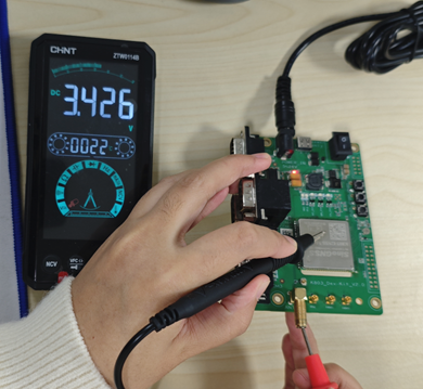
If the voltage is normal but satellites are still not acquired, the issue may be related to RF circuitry or module hardware.
Ø Abnormal voltage (missing or incorrect):
l Boards with external antenna power circuitry:
Inspect the RF bias network for short circuits, open circuits, or component-level issues.
l Boards powered directly by the GNSS module:
Proceed to ANT_IN pin verification.
3.2 ANT_IN Pin Voltage Check
Ø Action:
Measure the voltage at the module’s ANT_IN pin.
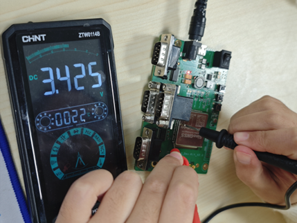
Ø Interpretation:
l Normal voltage indicates that the module output is functioning, and the RF trace between ANT_IN and the RF connector should be inspected.
l Abnormal or missing voltage typically indicates damage to the module’s internal current-limiting or protection circuitry.
4. Final Assessment
If the GNSS board still fails to acquire satellites after completing all the above steps, the issue can be identified as a GNSS module hardware fault.
Ø Recommended action:
Contact the COMNAV technical support for professional inspection and repair.
5. Summary
By following a structured troubleshooting sequence—from firmware verification to RF power diagnostics—most GNSS “no satellite” issues can be quickly isolated and resolved.
This methodology reflects COMNAV’s practical OEM support experience and is applicable across surveying, robotics, UAV, and other high-precision GNSS applications.
About ComNav Technology
ComNav Technology develops and manufactures GNSS OEM boards and receivers for high precision positioning demanded applications. Its technology already been used in a wide range of applications such as surveying, construction, machine control, agriculture, intelligent transportation, precise timing, deformation monitoring, unmanned system. With a team dedicated for the GNSS technology, ComNav Technology is trying its best to supply reliable and competitive products to worldwide customers. ComNav Technology has been listed on the Shanghai Stock Exchange (Science and Technology Board), securities :ComNav Technology (Compass Navigation), Stock code: 688592.
About SinoGNSS®
SinoGNSS® is the official trademark of ComNav Technology Ltd., registered in People's Republic of China, EU, USA and Canada. All other trademarks are the property of their respective owners.
About ComNavTech®
ComNavTech® is the official trademark of ComNav Technology Ltd., registered in People's Republic of China, EU, USA and Canada. All other trademarks are the property of their respective owners.