Command Introduction: “log sysconfig”
“Is there a way to view the current configuration of my module?” We met many clients are curious about the current configuration of SinoGNSS K8 OEM board, in today's article, we will introduce the most frequently used information about the system configuration. By command “log sysconfig”, clients can check basic configuration, rtk configuration and work mode like PPS, Event, and SBAS.
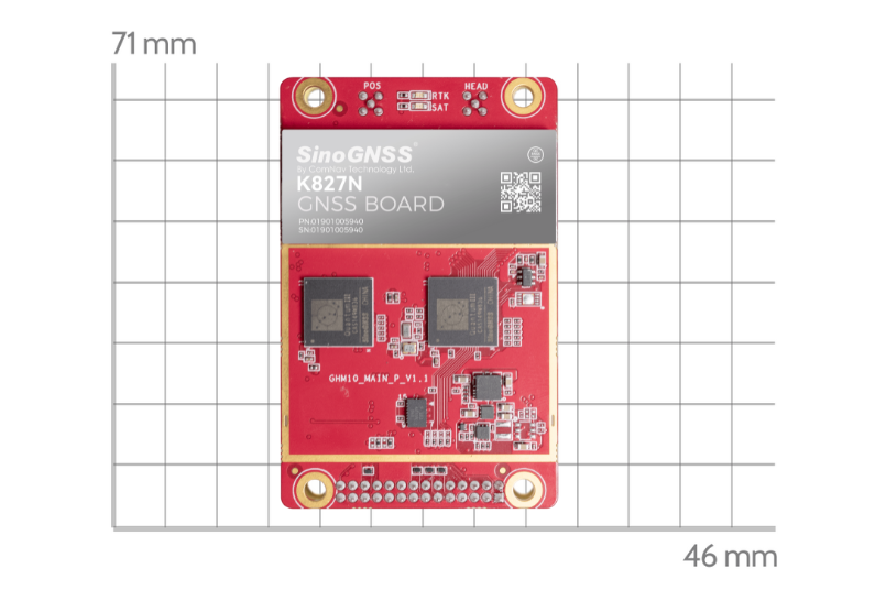
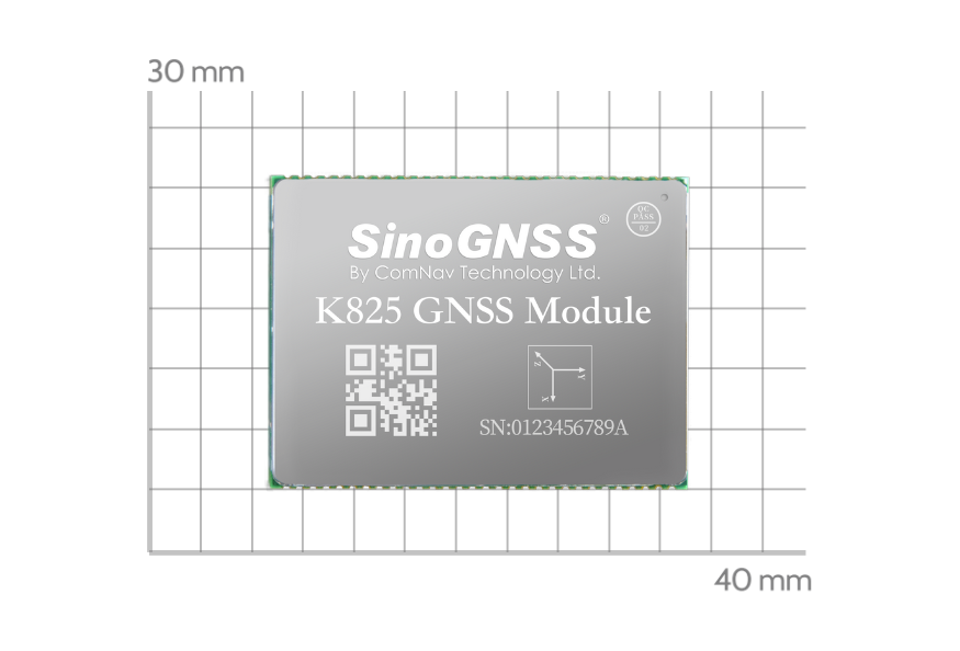
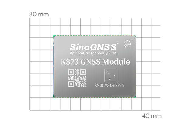
This command is suitable for most K8-series GNSS modules, for more information please visit the website: https://www.comnavtech.com/Products/12.html
Here shows with ComNav CRU software, to give command “log sysconfig” and its output messages.
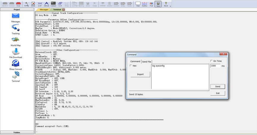
Log sysconfig
1 Basic configuration
In basic configuration, it shows the configuration of calculation rate, satellites cut angle, locked satellites and some other information.

● CPU frequency
In some cases high update rate observation, PVT or RTK is needed, the default CPU core frequency couldn't bear so huge calculation load, so a high frequency is necessary, at the same time, it means more power cost.
● PVT/PPP/RTK frequency
The message refer to PVT/PPP/RTK calculation rate.
In K8 series board, the default settings is 5HZ, if a higher or lower PVT update frequency is needed, this command could configure the PVT update rate at most 20hz.
| SET PVTFREQ Param1 | Param1 is valid PVT frequency in Hz: 1, 2, 5(default), 10, 20 |
| SET RTKFREQ Param1 | Param1 is valid RTK frequency in Hz: 1, 2, 5(default), 10, 20 |
Notice: PVT frequency should be higher than RTK frequency.
● GPS/BD2/GLO/GAL cut angle
These message sets the elevation cut-off angle for tracked. The board does not start automatically searching for a satellite until it rises above the cut-off angle. Tracked satellites that fall below the cut-off angle are no longer tracked unless they were manually assigned.
ECUTOFF 10 | the value of cutoff-angle (-90~90 degree) |
● Lockouted SVs
Prevent the board from using a satellite system. This message prevents the receiver from using satellites in the specified system in the solution computation.
| LOCKOUTSYSTEM [Param1] | [Param1]: GPS,GLAONASS,GALILEO,BD3,BD2,QZSS |
● CP Smooth PR
A method of combination of CP and PR, to get a higher quality observation.
SET CPSMOOTHPR [Param1] [Param2] [Param3] | Param1: smooth enable switch, ON/OFF Param2: smooth time constant, range from 10 ~ 200 seconds, default is 50s; Param3: tracking time threshold, range from 0 ~ 60 seconds, default is 15s. |
● Smoothed PVT
In single-point positioning, ComNav Technology have adopted an advanced smoothing filter to enhance pass to-pass accuracy, which need send commands as:
| Set smoothedpvt on | Enable smooth mode |
| Saveconfig | Save configuration |
● INS Control
The INS (Inertial Navigation System) Mode allows OEM modules to continuously output positioning information through IMU in a short time when losing satellites signal.
ENABLE: INS enabled; DISABLE: INS disabled
1/2/3/4/5/6/7/8: IMU axes type
Regarding IMU setup, you can refer to blog “ How to Enable GNSS+INS system on K8 series modules” by link: https://www.comnavtech.com/blogs_details/3.html
● CWI1/CWI2
K8 OEM modules support two channels to active anti-interference, it refers to CWI1 and CWI2. Clients can enable CWI by auto mode, or manually select the channels. Details can refer to ComNav OEM commands list: CNT-OEM-RM001_Rev_2.3_20220507
| SET CWI AUTO Param1 | Param1: 0: off, default 1: channel 1 on 2: channel 2 on 3: channel 1&2 on |
| SET CWI MANUAL Param1 Param2 Param3 | Param1: 1/2/3/4/5/6/7/8/9/10 Param2: 0/1 Param3: 0/1 |
2 RTK configuration
This part is the receiver's processing scheme for RTK, and the current working status information.

● RTK Time Out
This command is used to set the maximum age of RTK data to use when operating as a rover station. RTK data received that is older than the specified time is ignore.
After rtk disconnects the differential, after 200 seconds, it will exit fixed status.
| RTKTIMEOUT [time-delay] | time-delay: less than 200s, default 200s |
● RTKFIXHOLDTIME
This command is used to set the maximum age of RTK fixed data to use when operating as a rover station. RTK fixed data received that is older than the specified time is ignored.
| RTKFIXHOLDTIME [time-delay] | time-delay: less than 200s and more than 5s, default value is 20s |
● RtkSourceType
This command is used to identify from which base station to accept RTK differential corrections. This is useful when the receiver is receiving corrections from multiple base stations.
| RTKSOURCE <type> [stn id] | type: AUTO/RTCMV3 stn id: --AUTO: ANY --RTCMV3: 0 <= RTCMV3 station ID <=4095 or ANY |
● RtkRefStnType
This command sets the station ID value for the receiver when it is transmitting corrections. This allows for the easy identification of which base station was the source of the data.
| DGPSTXID <type> <ID> | type: AUTO/RTCMV3 stn id: --AUTO: ANY --RTCMV3: 0 <= RTCMV3 station ID <=4095 or ANY |
● App Scene
This command can be used to set the application mode. In different modes, the RTK engine should process different styles of observation data to improve the performance of the RTK engine.
For example, if you use ComNav K8 series as drone gps module, there will setup APP Scene mode to air.
| SET APPSCENE <mode> | Mode: survey/robot/car/air/space |
| Saveconfig | Save configuration |
Other options are suggested to keep as default.
3 COM configuration
These message shows the status(normal mode or differential mode) for all COM ports.

For more details please have a check of the blog:
https://www.comnavtech.com/blogs_details/8.html
4 PPS configuration
PPS, which stands for "Pulse Per Second," is a precise timing signal often used in various applications that require accurate time synchronization.

With PPS function, you can set the polarity, period and pulse-width of PPS output.
Format: PPSCONTROL <switch> <polarity> <period> <pulse-width>
| ppscontrol enable positive 1 1000 | Set PPS as high level pulse with 1ms width per second |
| Saveconfig | Save configuration |
● <switch> supports “enable” or “disable”, notice that “disable” is invalid.
● <polarity> supports “positive” and “negative”, “positive” means high level pulse mode and “negative” means low level pulse mode.
● <period> in seconds, the update rate can be up to 10Hz.
● <pulse-width> in microseconds, pulse-width should be less than half of period.
5 EVENT configuration
Event refers to a significant occurrence, action, or incident that triggers a response or a change in the system's state. Events can be both planned and spontaneous, and they are often used to capture and manage important moments within a system.

Format: MARKCONTROL <signal> <switch> [polarity] [timebias] [timeguard]]
| markcontrol mark1 enable negative 0 0 | Open Event1 marker |
| Log marktimea onnew | Time of mark input event |
| Log markposa onnew | Position at time of mark input event |
| Saveconfig | Save configuration |
● <signal> supports the key words “mark1” and “mark2”.
● <switch> supports the key words “enable” and “disable”.
● [polarity] supports the key words “positive” and “negative”, which separately represent “positive pulse” and “negative pulse”.
● [timebias] A constant time bias in nanoseconds can be applied to each event pulse. Typically this is used to account for a transmission delay.
● [timeguard] The time guard specifies the minimum number of milliseconds between pulses. This is used to coarsely filter the input pulses.
6 PVT configuration
For PVT configuration, parameters normally used for R&D debug.

7 Parameter Offset configuration
In this section, it provides parameters for datum and some offset value.

● PJK Parameter: A:6378137.000, 1/F:298.257223563, B0:0.000000deg, L0:120.000000, N0:0.000, E0:500000.000.
| SET PJKPARA Param1 … Param6 | Param1 … Param6: 1)A: the long axle of the earth 2)1/F: F is the Earth flat rate 3)B0: reference latitude(in degree) 4)L0: reference longitude(in degree) 5)N0: reference north coordinate 6)E0: reference east coordinate |
● HeadingOffset
This command is used to add an offset in degree in the heading and pitch values of the HEADING, GPHDT, GPNAV, GPTRA, GPYBM and PTNL,AVR logs.
Both heading offset and pitch offset have the default values of 0 degree.
HEADINGOFFSET<headingoffsetindeg><pitchoffsetindeg> | Heading offset value, ranges from -180.0~+180.0°; Pitch offset value, ranges from -90.0~+90.0°. |
8 SBAS Configuration
SinoGNSS K8-series all support SBAS function, please refer to the blog “How to start with SBAS mode?” by link: https://www.comnavtech.com/blogs_details/1.html

9 Other Configuration

● IMU(INS)
Smoothed DR: OFF // INS smoothing DR TimeOut : 300 // INS hold time
DR InitV: 3.0 // Inertial navigation initialization speed
DR LeverArm: 0.00, 0.00, 0.00 // INS arm value
Regarding IMU setup, you can refer to blog “ How to Enable GNSS+INS system on K8 series modules” by link: https://www.comnavtech.com/blogs_details/3.html
● PPP
PPP Source: B2b //B2b/HAS/RTCM switchable
PPP CoordSys: ITRF //ITRF/WGS84 switchable
Contact ComNav for latest PPP-HAS/B2b firmware version.
Parameters that are not explicitly mentioned are considered reserved or not be allowed to be disclosed to the public.
About ComNav Technology
ComNav Technology develops and manufactures GNSS OEM boards and receivers for high precision positioning demanded applications. Its technology already been used in a wide range of applications such as surveying, construction, machine control, agriculture, intelligent transportation, precise timing, deformation monitoring, unmanned system. With a team dedicated for the GNSS technology, ComNav Technology is trying its best to supply reliable and competitive products to worldwide customers. ComNav Technology has been listed on the Shanghai Stock Exchange (Science and Technology Board), securities :ComNav Technology (Compass Navigation), Stock code: 688592.
About SinoGNSS®
SinoGNSS® is the official trademark of ComNav Technology Ltd., registered in People's Republic of China, EU, USA and Canada. All other trademarks are the property of their respective owners.
About ComNavTech®
ComNavTech® is the official trademark of ComNav Technology Ltd., registered in People's Republic of China, EU, USA and Canada. All other trademarks are the property of their respective owners.
